
Kubernetes is the default orchestration layer for containerized workloads, but its moving parts confuse newcomers and experienced engineers alike. A Kubernetes cluster architecture diagram should answer three questions at once: who makes scheduling decisions, where containers actually run, and how traffic reaches a pod that may restart at any time.
Below we break down the control plane, worker nodes, networking primitives (Service, Ingress, CNI), and the deploy path from CI — then show how to lay it out visually for design docs, onboarding, and incident reviews.
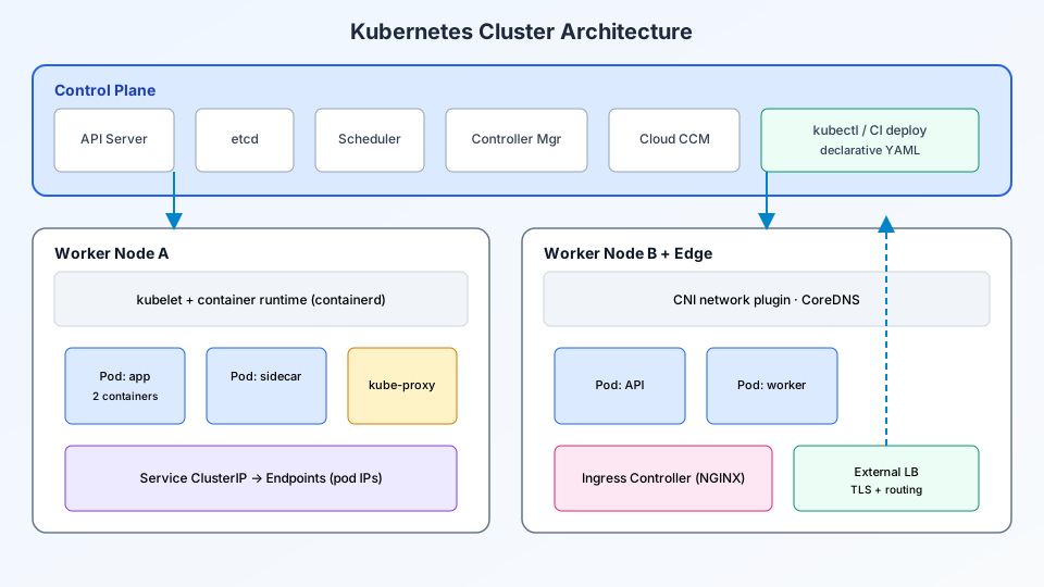
Control plane: the brain of the cluster
Group these components inside a labeled “control plane” boundary at the top of your diagram:
- API Server — the only component you talk to via
kubectl; validates and persists desired state. - etcd — consistent key-value store holding all cluster state; backup and HA matter here.
- Scheduler — assigns pods to nodes based on resources, affinity, taints, and topology.
- Controller Manager — reconciliation loops (ReplicaSet, Deployment, Node lifecycle).
- Cloud Controller Manager — integrates with cloud LB, routes, and disk attach APIs when on AWS/GCP/Azure.
Managed services (EKS, GKE, AKS) hide parts of this stack, but interviews and troubleshooting still expect you to know which function lives where. Annotate “managed” vs “self-operated” on each box for your environment.
Worker nodes: where pods execute
Each worker node diagram block should contain:
- kubelet — agent that starts/stops containers defined in pod specs.
- Container runtime — containerd or CRI-O pulling images from a registry.
- kube-proxy — implements Service VIP routing via iptables or IPVS.
- CNI plugin — assigns pod IPs and network policies (Calico, Cilium, etc.).
- Pods — one or more containers sharing network namespace and volumes.
Never draw traffic going directly to pod IPs from the public internet — show Ingress or LoadBalancer Service in front unless you are documenting a deliberate hostNetwork exception.
Networking: Services and Ingress
Pods are ephemeral; Services provide stable DNS names and virtual IPs:
| Resource | Scope | Use on diagram |
|---|---|---|
| ClusterIP | Internal only | Microservice-to-microservice arrows |
| NodePort | Host port exposure | Lab clusters; rarely public prod |
| LoadBalancer | Cloud LB provisioned | External API entry without Ingress |
| Ingress | HTTP routing rules | Host/path → Service backend |
Place an Ingress controller (NGINX, Traefik, AWS LB controller) at the edge with TLS termination, then route to Services backed by pod endpoints. This mirrors how you would place an L7 load balancer in a VM-based architecture — see our load balancer architecture guide for parallel concepts.
Deploy path from CI/CD
Add a side arrow from your pipeline to the API server:
- Git push triggers CI build and image push to a registry.
- CD applies Deployment YAML (GitOps with Argo CD/Flux or imperative
kubectl apply). - Controllers roll out new ReplicaSets with rolling update strategy.
- Readiness probes gate traffic until new pods pass health checks.
Animated rollouts help teammates see old pods drain while new ones register — you can export that sequence using the workflow in convert flowchart to animated diagram.
Storage and configuration (when to expand the diagram)
- ConfigMaps & Secrets — mounted as env vars or files; show external secret managers (Vault, SSM) feeding Kubernetes Secrets.
- PersistentVolumeClaims — stateful sets for databases; note whether data lives outside the cluster (managed RDS).
- Horizontal Pod Autoscaler — metrics server → HPA → Deployment replica count.
Multi-node and multi-AZ layout
For production, duplicate worker node groups across availability zones. Draw the scheduler placing pod replicas anti-affinity across zones. Include CoreDNS as a cluster add-on resolving *.svc.cluster.local names.
Operational concerns to annotate
- Resource requests/limits — prevent noisy neighbors; show quotas at namespace level in platform diagrams.
- Network policies — default deny east-west traffic in zero-trust designs.
- Observability — DaemonSet agents shipping logs/metrics/traces to Prometheus, Grafana, or vendor backends.
- Upgrade strategy — control plane version skew rules vs node pool cordon/drain.
Example diagram prompt
Production Kubernetes on AWS: EKS control plane (managed)
3 worker nodes in different AZs, kubelet + containerd
Deployment with 6 pods behind ClusterIP Service
NGINX Ingress Controller → ALB → internet users
GitHub Actions CI pushes image to ECR, Argo CD syncs manifests
Show Prometheus + Grafana DaemonSets.
FAQ
What is the difference between a pod and a container?
A pod wraps one or more containers that share storage and network. Sidecar containers (logging, mesh proxies) belong in the same pod box on your diagram.
Do I need Ingress if I use a cloud LoadBalancer Service?
LoadBalancer Services expose one Service per LB — fine for small setups. Ingress consolidates many HTTP routes behind one entry point with shared TLS and routing rules.
How does this relate to microservice architecture diagrams?
Application architecture shows services and data stores; Kubernetes architecture shows how those services map to Deployments, Services, and nodes. Link both diagrams in docs — application logic in one, platform placement in the other — as done in broader architecture mapping guides.
Conclusion
A useful Kubernetes cluster architecture diagram separates control plane responsibilities from worker execution, shows stable Service endpoints instead of pod IPs, and documents the CI/CD path that mutates desired state. Whether you run managed EKS or bare-metal k8s, the same boxes help teams reason about scheduling, networking, and deploy safety — before an incident forces the conversation.
Draw your cluster architecture
Use ByteDiagram to lay out control plane, nodes, Ingress, and observability stacks — then animate a rolling deploy for your next tech talk.
Open Diagram Editor